Introduction
Directional couplers are important passive components used in RF and microwave systems to sample a portion of the electromagnetic power travelling through a transmission line. They allow engineers to monitor forward and reflected signals without significantly disturbing the main signal path.
These components are widely used in RF transmitters, power amplifiers, antenna measurement systems, communication equipment, radar systems and laboratory test setups.
Understanding the operating principle and key performance parameters of a directional coupler is essential when selecting the right component for an RF application.
1. What Is an RF Directional Coupler?
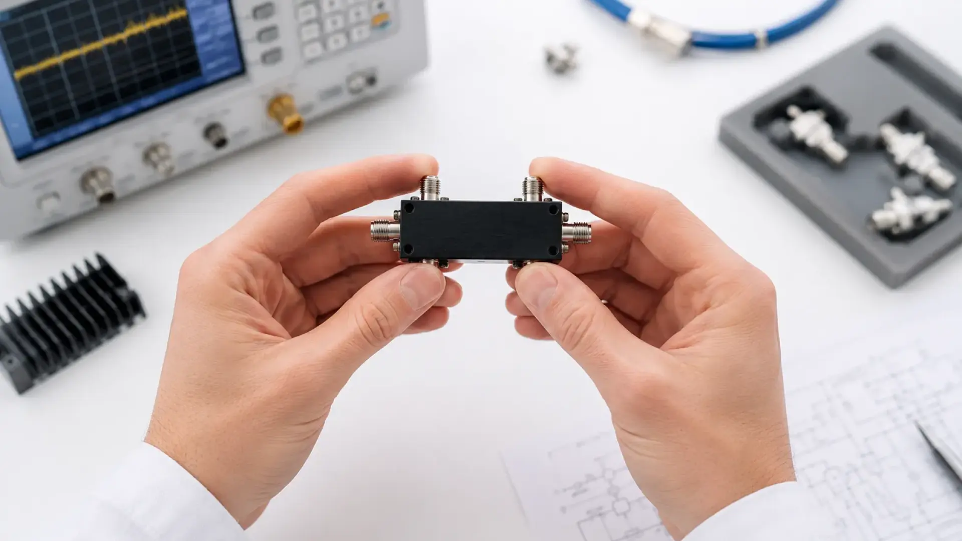
An RF directional coupler is a passive four-port network designed to transfer a controlled fraction of power from a main transmission line to a secondary port. The amount of transferred power is determined by its coupling factor.
A typical directional coupler has four ports:
- Input Port: Receives the incoming RF signal.
- Through Port: Carries most of the input signal towards the load.
- Coupled Port: Samples a specified fraction of the travelling signal.
- Isolated Port: Ideally receives very little power from the input signal travelling in the forward direction.
The actual port arrangement and orientation depend on the coupler design and the direction of signal propagation.
2. Working Principle of a Directional Coupler
Directional couplers operate by using electromagnetic coupling between two transmission-line structures or through another suitable RF coupling mechanism.
When an RF signal enters the input port, most of its power travels towards the through port. A smaller, controlled portion is transferred to the coupled port.
The coupler is designed to distinguish between signals travelling in opposite directions. This directional behaviour makes it possible to sample forward and reverse power using suitable coupler arrangements.
For example, in a transmitter system, a directional coupler can monitor the forward power delivered to an antenna and the reflected power caused by impedance mismatch.
3. Important Performance Parameters
3.1 Coupling Factor
Coupling factor describes the ratio between the input power and the power measured at the coupled port. It is commonly expressed in decibels.
Coupling Factor (dB) = 10 log10(Pin / Pcoupled)
Where Pin is the input power and Pcoupled is the power available at the coupled port under the specified measurement conditions.
For example, a nominal 20 dB coupler ideally provides a coupled-port power level 20 dB below the input power, assuming matched conditions and the specified coupling orientation.
3.2 Directivity
Directivity indicates how effectively a directional coupler distinguishes between forward and reverse travelling waves.
Higher directivity generally means better separation of the desired coupled signal from unwanted leakage associated with the opposite direction of propagation.
This parameter is particularly important when measuring reflected power or calculating antenna return loss and VSWR.
3.3 Insertion Loss
Insertion loss represents the reduction in signal power through the main transmission path when the coupler is inserted into the system.
Lower insertion loss is generally desirable because it minimizes the impact of the coupler on the primary RF signal.
3.4 Isolation
Isolation describes the attenuation between the input port and the isolated port under the specified operating conditions.
Good isolation helps reduce unwanted signal leakage and contributes to accurate directional sampling.
3.5 Return Loss and VSWR
Return loss and Voltage Standing Wave Ratio (VSWR) are used to evaluate impedance matching at the coupler ports.
Good impedance matching helps minimize reflections and supports predictable RF power transfer.
4. Common Types of Directional Couplers
4.1 Coupled-Line Directional Coupler
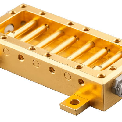
Coupled-line directional couplers use two nearby transmission lines to achieve electromagnetic coupling. They are commonly implemented using microstrip, stripline or other planar transmission-line technologies.
The coupling characteristics depend on factors such as line spacing, coupled-line length, substrate properties and operating frequency.
4.2 Branch-Line Coupler
A branch-line coupler uses interconnected transmission-line sections to divide or combine RF signals. It is commonly used in quadrature hybrid applications, where signals with a nominal 90-degree phase relationship are required.
4.3 Waveguide Directional Coupler
Waveguide directional couplers are used in microwave and millimetre-wave systems. Their structures are designed for operation within specified waveguide frequency bands and power-handling requirements.
4.4 Resistive and Other Coupler Configurations
Other RF sampling structures use resistive, hybrid or specialized coupling arrangements. The appropriate configuration depends on bandwidth, directivity, insertion loss, power handling and application requirements.
5. Applications of RF Directional Couplers
Directional couplers are used in many RF and microwave engineering applications.
- RF Power Monitoring: Sampling forward and reflected power in transmitters and RF amplifiers.
- Antenna Measurement: Monitoring incident and reflected signals during antenna testing.
- Power Amplifier Testing: Measuring signal levels and monitoring RF system performance.
- Network Analyzers: Supporting signal sampling and measurement architectures.
- Communication Systems: Monitoring signal paths in wireless and microwave equipment.
- Laboratory Test Setups: Providing controlled RF signal samples for measurement instruments.
6. How to Select the Right Directional Coupler
Choosing a directional coupler requires evaluating the complete set of electrical and mechanical requirements.
Important selection criteria include:
- Frequency Range: Ensure that the operating frequency covers the required RF band.
- Coupling Factor: Select a suitable sampling level for the connected measurement instrument.
- Directivity: Consider the required separation between forward and reverse signals.
- Insertion Loss: Check the maximum acceptable loss in the main transmission path.
- Power Handling: Verify continuous-wave and peak power limits where applicable.
- Impedance: Confirm compatibility with the system impedance, commonly 50 ohms.
- Connectors: Select compatible RF connector types and mechanical interfaces.
- Operating Conditions: Consider temperature, mounting and environmental requirements.
7. Practical Measurement Using RF Test Equipment
Directional coupler performance can be evaluated using a Vector Network Analyzer (VNA) and suitable RF measurement accessories.
Depending on the coupler configuration, engineers can measure its S-parameters to characterize transmission, coupling, isolation and port matching.
- S21: Commonly used to evaluate transmission from port 1 to port 2.
- S31: Can be used to characterize coupling from port 1 to port 3 in a conventional four-port arrangement.
- S41: Can be used to evaluate isolation from port 1 to port 4.
- S11: Used to evaluate input-port matching.
These examples assume a conventional port numbering arrangement. Always confirm the device datasheet and port definitions before interpreting measurements.
Proper VNA calibration, correct port termination, suitable test cables and careful connector handling are important for reliable results.
8. Common Selection and Measurement Mistakes
- Selecting a coupler with an unsuitable frequency range.
- Ignoring directivity when measuring low reflected-power levels.
- Using an incorrect coupling factor when configuring a power measurement system.
- Exceeding the rated RF input power.
- Leaving unused ports improperly terminated.
- Ignoring connector compatibility and calibration requirements.
Careful evaluation of these factors helps avoid inaccurate measurements and unexpected RF system performance.
Conclusion
Directional couplers are essential components for monitoring and controlling RF signal paths. Their ability to sample travelling waves makes them useful in transmitters, amplifiers, antenna measurement systems and laboratory test environments.
Understanding coupling factor, directivity, insertion loss, isolation and return loss helps engineers select the appropriate component for their application.
Explore RF Components and Measurement Solutions from Metix RF
Metix RF provides RF and microwave components, test equipment, measurement solutions and engineering services for research, development and industrial applications.
Explore our RF product range or visit Metix RF to learn more.