Introduction
RF attenuators are passive components used to reduce the power level of radio-frequency and microwave signals by a specified amount. They help control signal levels, protect sensitive equipment, improve impedance matching and maintain suitable operating conditions in RF systems.
Attenuators are commonly used in RF laboratories, communication systems, radar equipment, microwave test benches, transmitter chains and receiver front ends.
Understanding attenuation, frequency range, impedance, power handling and return loss is important when selecting an appropriate attenuator for an RF application.
1. What Is an RF Attenuator?
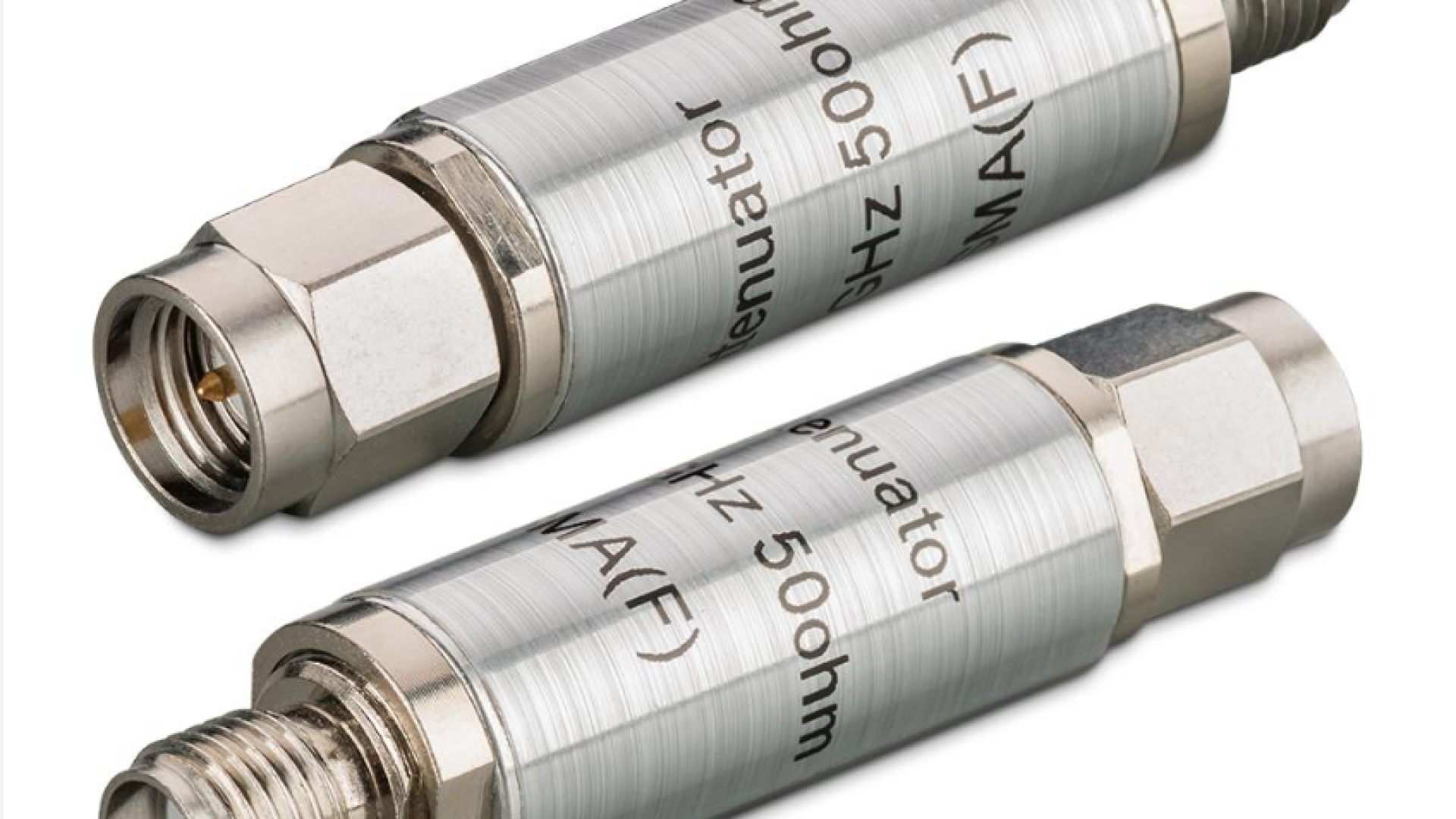
An RF attenuator is a passive two-port component designed to reduce the power or amplitude of an RF signal while maintaining a specified impedance match over its operating frequency range.
For example, a 10 dB attenuator reduces the output power by 10 dB relative to its input power under matched operating conditions.
Attenuators are available in different attenuation values, frequency ranges, connector configurations and power ratings.
Unlike an amplifier, an attenuator does not increase signal power. It introduces a controlled loss between the input and output ports.
2. Understanding Attenuation
Attenuation describes the reduction in signal power between the input and output of a component. It is commonly expressed in decibels (dB).
2.1 Power Attenuation Formula
For power measurements, attenuation is calculated as:
A (dB) = 10 log10 (Pin / Pout)
Where:
- Pin is the input power.
- Pout is the output power.
- A is the attenuation in decibels.
For example, consider a 10 dB attenuator with an input power of 100 mW. Under ideal matched conditions, the output power is 10 mW.
2.2 Voltage Attenuation Formula
The corresponding voltage ratio for equal reference impedances is:
A (dB) = 20 log10 (Vin / Vout)
This relationship is useful when comparing RF voltage levels across matched transmission lines.
2.3 Common Attenuation Values
| Attenuation |
Output Power Ratio |
Power Remaining |
| 3 dB |
0.501 |
50.1% |
| 6 dB |
0.251 |
25.1% |
| 10 dB |
0.100 |
10% |
| 20 dB |
0.010 |
1% |
| 30 dB |
0.001 |
0.1% |
3. Types of RF Attenuators
RF attenuators are available in different configurations depending on the application, required attenuation range and level of control.
3.1 Fixed Attenuators
Fixed attenuators provide a predetermined attenuation value that cannot be adjusted during normal operation.
Common values include 3 dB, 6 dB, 10 dB, 20 dB and 30 dB. They are widely used for signal-level adjustment, equipment protection and RF measurement setups.
3.2 Variable Attenuators
Variable attenuators allow the attenuation level to be adjusted over a specified range.
They are useful when signal levels need to be controlled during testing, calibration, receiver sensitivity measurements or system characterization.
3.3 Step Attenuators
Step attenuators provide selectable attenuation values in defined increments. Depending on the design, the attenuation may be adjusted manually using switches or electronically using control signals.
They are commonly used in automated RF test systems and receiver evaluation setups.
4. Working Principle of RF Attenuators
An RF attenuator works by introducing a controlled amount of signal loss between its input and output ports. This is generally achieved using resistive networks or other frequency-dependent circuit structures.
In a matched RF system, the attenuator is designed to maintain the specified characteristic impedance while reducing the transmitted signal level.
4.1 Resistive Attenuator Networks
Resistive attenuators use carefully selected resistor networks to produce a desired attenuation while maintaining impedance matching.
Common resistive configurations include:
- T-type attenuator networks
- Pi-type attenuator networks
- L-type attenuator networks
4.2 T-Type Attenuator
A T-type attenuator uses two series resistors and one shunt resistor. It is designed to provide a specified attenuation while maintaining the required input and output impedance.
4.3 Pi-Type Attenuator
A Pi-type attenuator uses two shunt resistors and one series resistor. Its configuration resembles the Greek letter pi and is commonly used in impedance-matched RF circuits.
5. Key RF Attenuator Specifications
Selecting an RF attenuator requires evaluating several electrical and mechanical parameters. The correct specification depends on the operating frequency, power level and measurement environment.
5.1 Attenuation Value
The attenuation value indicates how much the input signal is reduced. It is normally specified in decibels (dB).
5.2 Frequency Range
The frequency range defines the frequencies over which the attenuator is designed to operate within its specified performance limits.
5.3 Characteristic Impedance
RF attenuators are commonly designed for 50-ohm systems. Some applications use 75-ohm systems, particularly in specific video and cable distribution environments.
5.4 Power Handling
Power handling specifies the maximum RF input power that the attenuator can safely dissipate under the stated operating conditions.
5.5 VSWR and Return Loss
Voltage Standing Wave Ratio (VSWR) and return loss describe the impedance matching performance of an RF attenuator.
Lower VSWR and higher return loss generally indicate better impedance matching.
5.6 Insertion Loss and Attenuation Accuracy
Insertion loss and attenuation accuracy are important when evaluating the actual signal reduction and its deviation from the specified nominal value.
5.7 Connector Type
RF attenuators are available with different connector interfaces, including SMA, N-type, BNC and other RF connector types. Connector selection should match the test setup and operating frequency.
5.8 Temperature Range
The operating temperature range defines the environmental conditions under which the attenuator is specified to operate.
6. Applications of RF Attenuators
RF attenuators are essential components in many RF and microwave applications. They help manage signal levels and improve the reliability of measurement and communication systems.
6.1 RF Testing and Measurement
Attenuators are used with vector network analyzers, spectrum analyzers and signal generators to control signal levels and protect measurement equipment.
6.2 Communication Systems
In communication systems, attenuators help adjust signal levels between different RF stages and support controlled signal distribution.
6.3 Radar Systems
Radar testing and evaluation setups use attenuators to control RF signal levels and simulate different signal conditions.
6.4 Receiver Testing
Attenuators are used during receiver sensitivity and dynamic range testing to provide controlled input signal levels.
6.5 RF Laboratory Setups
RF laboratories use attenuators for calibration, signal conditioning, equipment protection and repeatable measurement configurations.
7. How to Select an RF Attenuator
Choosing the correct RF attenuator requires matching its electrical specifications to the intended application.
- Frequency range: Select an attenuator that covers the complete operating frequency range.
- Attenuation value: Determine the required signal reduction in dB.
- Impedance: Match the attenuator impedance to the RF system, commonly 50 ohms.
- Power handling: Ensure the attenuator can safely handle the maximum input power.
- VSWR and return loss: Check the matching performance required for the application.
- Connector interface: Select compatible RF connectors for the measurement setup.
- Environmental conditions: Check the operating temperature and other relevant conditions.
RF Attenuator Selection Checklist
| Parameter |
What to Check |
| Frequency |
Required operating frequency range |
| Attenuation |
Required dB value |
| Impedance |
50 ohms or 75 ohms as required |
| Power |
Maximum input power and duty conditions |
| VSWR |
Specified impedance matching performance |
| Connector |
Compatible connector interface |
8. Conclusion
RF attenuators are fundamental passive components used to control signal levels in RF and microwave systems. They are important in laboratory measurements, communication equipment, radar systems, receiver testing and RF development.
Understanding attenuation values, frequency range, impedance, power handling, VSWR and connector specifications helps engineers select the appropriate attenuator for a particular application.
Whether used in a laboratory test bench or an integrated RF system, a properly selected attenuator supports reliable signal control and measurement performance.
Explore METIX RF solutions for RF components, attenuators and microwave test and measurement equipment.